- 您现在的位置:买卖IC网 > Sheet目录877 > RPER72A225K7C1F03B (Murata Electronics North America)CAP CER 2.2UF 100V 10% RADIAL
�� �
�
�!� Note� ?� Please� read� rating� and� !� CAUTION� (for� storage,� operating,� rating,� soldering,� mounting� and� handling)� in� this� catalog� to� prevent� smoking� and/or� burning,� etc.�
�?� This� catalog� has� only� typical� speci?cations.� Therefore,� please� approve� our� product� speci?cations� or� transact� the� approval� sheet� for� product� speci?cations� before� ordering.�
�C49E.pdf�
�Mar.12,2014�
�1�
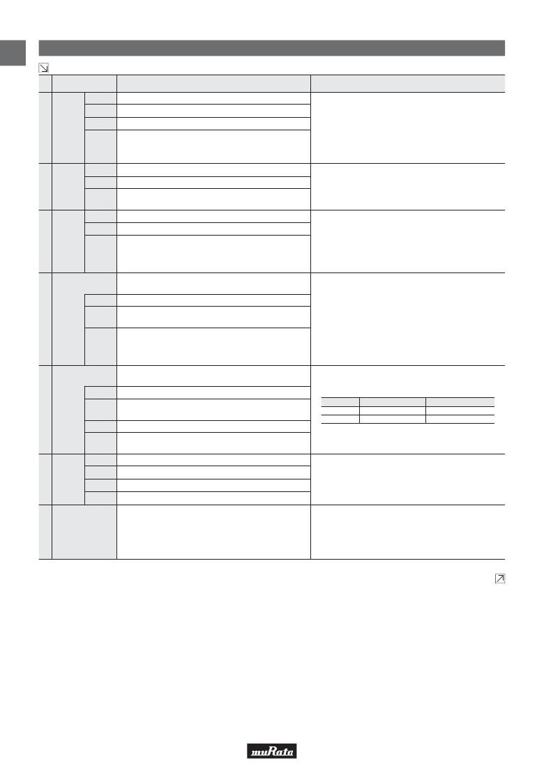
�High� Dielectric� Constant� Type� Speci?cations� and� Test� Methods�
�Continued� from� the� preceding� page.�
�No.� AEC-Q200� Test� Item�
�Specifications�
�AEC-Q200� Test� Method�
�Appearance� No� defects� or� abnormalities�
�Capacitance� Within� the� specified� tolerance�
�Per� MIL-STD-202� Method� 215�
�Solvent� 1:� 1� part� (by� volume)� of� isopropyl� alcohol�
�3� parts� (by� volume)� of� mineral� spirits�
�10�
�Resistance� D.F.�
�to� Solvents�
�I.R.�
�0.025� max.�
�More� than� 10,000M� Ω� or� 500M� Ω� ·� μF� (Whichever� is� smaller)�
�Solvent� 2:� Terpene� defluxer�
�Solvent� 3:� 42� parts� (by� volume)� of� water�
�1� part� (by� volume)� of� propylene� glycol�
�monomethyl� ether�
�1� part� (by� volume)� of� monoethanolamine�
�Appearance� No� defects� or� abnormalities�
�Three� shocks� in� each� direction� should� be� applied� along�
�11�
�Mechanical� Capacitance� Within� the� specified� tolerance�
�Shock�
�D.F.� 0.025� max.�
�3� mutually� perpendicular� axes� of� the� test� specimen� (18� shocks).�
�The� specified� test� pulse� should� be� Half-sine� and� should�
�have� a� duration:� 0.5ms,� peak� value:� 1,500G� and� velocity�
�change:� 4.7m/s.�
�12� Vibration�
�Appearance� No� defects� or� abnormalities�
�Capacitance� Within� the� specified� tolerance�
�The� capacitor� should� be� subjected� to� a� simple� harmonic� motion�
�having� a� total� amplitude� of� 1.5mm,� the� frequency� being� varied�
�uniformly� between� the� approximate� limits� of� 10� and� 2,000Hz.�
�The� frequency� range,� from� 10� to� 2,000Hz� and� return� to� 10Hz,�
�D.F.�
�Resistance� to�
�Soldering� Heat�
�0.025� max.�
�The� measured� and� observed� characteristics� should� satisfy� the�
�specifications� in� the� following� table.�
�should� be� traversed� in� approximately� 20min.� This� motion�
�should� be� applied� for� 12� items� in� each� 3� mutually� perpendicular�
�directions� (total� of� 36� times).�
�Appearance� No� defects� or� abnormalities�
�The� lead� wire� is� immersed� in� the� melted� solder� 1.5� to� 2mm�
�from� the� main� body� at� 260±5°C� for� 10±1s.� The� specified� items�
�13�
�Capacitance�
�Change�
�Dielectric�
�Strength�
�(Between�
�Wthin� ±7.5%�
�No� defects�
�are� measured� after� 24±2h.�
�Perform� the� heat� treatment� at� 150+0/-10°C� for� 60±5min� and�
�then� let� sit� for� 24±2h� at� *room� condition.�
�terminals)�
�Thermal� Shock�
�The� measured� and� observed� characteristics� should� satisfy� the�
�specifications� in� the� following� table.�
�Perform� the� 300� cycles� according� to� the� two� heat� treatments�
�listed� in� the� following� table� (Maximum� transfer� time� is� 20s.).�
�Appearance� No� defects� or� abnormalities�
�Let� sit� for� 24±2h� at� *room� condition,� then� measure.�
�14�
�Capacitance�
�Change�
�Within� ±12.5%�
�Step�
�Temp.� (°C)�
�Time� (min.)�
�1�
�-55+0/-3�
�15±3�
�2�
�125+3/-0�
�15±3�
�D.F.�
�0.05� max.�
�I.R.�
�1,000M� Ω� or� 50M� Ω� ·� μF� min.� (Whichever� is� smaller)�
�Perform� the� heat� treatment� at� 150+0/-10°C� for� 60±5min� and�
�then� let� sit� for� 24±2h� at� *room� condition.�
�Appearance� No� defects� or� abnormalities�
�Capacitance� Within� the� specified� tolerance�
�15� ESD�
�D.F.�
�I.R.�
�0.025� max.�
�More� than� 10,000M� Ω� or� 500M� Ω� ·� μF� (Whichever� is� smaller)�
�Per� AEC-Q200-004�
�Should� be� placed� into� steam� aging� for� 8h±15min.�
�The� terminal� of� capacitor� is� dipped� into� a� solution� of� ethanol�
�16� Solderability�
�Lead� wire� should� be� soldered� with� uniform� coating� on� the� axial�
�direction� over� 95%� of� the� circumferential� direction.�
�(JIS� K� 8101)� and� rosin� (JIS� K� 5902)� (25%� rosin� in� weight�
�propotion).� Immerse� in� solder� solution� for� 2±0.5� seconds.�
�In� both� cases� the� depth� of� dipping� is� up� to� about� 1.5� to� 2mm�
�from� the� terminal� body.�
�*� “room� condition”� Temperature:� 15� to� 35°C,� Relative� humidity:� 45� to� 75%,� Atmosphere� pressure:� 86� to� 106kPa�
�Continued� on� the� following� page.�
�18�
�发布紧急采购,3分钟左右您将得到回复。
相关PDF资料
RPP20-4824S-M
CONV DC/DC 20W 36-75VIN 24VOUT
RPP20-4824SW-M
CONV DC/DC 20W 18-75VIN 24VOUT
RPP30-4824S-M
CONV DC/DC 30W 36-75VIN 24VOUT
RPP30-4824SW-M
CONV DC/DC 30W 18-75VIN 24VOUT
RPP40-4824S-B
CONV DC/DC 40W 36-75V 24VOUT
RPP40-4824SW-T
CONV DC/DC 40W 18-75V 24VOUT
RPP50-4824S-T
CONV DC/DC 50W 36-75VIN 24VOUT
RPR20-483.3S-B
CONV DC/DC 20W 25-75VIN 3.3VOUT
相关代理商/技术参数
RPER72A271K1A1D02B
功能描述:多层陶瓷电容器MLCC - 含引线 270pF 100volt X7R +/-10% RoHS:否 制造商:AVX 电容:470 pF 容差:10 % 电压额定值:3 kV 端接类型:Radial 工作温度范围: 温度系数/代码:X7R 引线间隔:5.08 mm 产品:Automotive MLCCs 引线类型:
RPER72A271K2P1B03B
功能描述:多层陶瓷电容器MLCC - 含引线 270pF 100volts X7R 10% 2.5mm L/S RoHS:否 制造商:AVX 电容:470 pF 容差:10 % 电压额定值:3 kV 端接类型:Radial 工作温度范围: 温度系数/代码:X7R 引线间隔:5.08 mm 产品:Automotive MLCCs 引线类型:
RPER72A272K1A1D02B
功能描述:多层陶瓷电容器MLCC - 含引线 2700pF 100volt X7R +/-10% RoHS:否 制造商:AVX 电容:470 pF 容差:10 % 电压额定值:3 kV 端接类型:Radial 工作温度范围: 温度系数/代码:X7R 引线间隔:5.08 mm 产品:Automotive MLCCs 引线类型:
RPER72A272K2P1A03B
功能描述:多层陶瓷电容器MLCC - 含引线 2700pF 100volts X7R 10% 2.5mm L/S RoHS:否 制造商:AVX 电容:470 pF 容差:10 % 电压额定值:3 kV 端接类型:Radial 工作温度范围: 温度系数/代码:X7R 引线间隔:5.08 mm 产品:Automotive MLCCs 引线类型:
RPER72A331K1A1D03B
功能描述:多层陶瓷电容器MLCC - 含引线 330pF 100volts X7R 10% 2.5mm L/S RoHS:否 制造商:AVX 电容:470 pF 容差:10 % 电压额定值:3 kV 端接类型:Radial 工作温度范围: 温度系数/代码:X7R 引线间隔:5.08 mm 产品:Automotive MLCCs 引线类型:
RPER72A331K1A1D25B
功能描述:多层陶瓷电容器MLCC - 含引线 330pF 100volts X7R 10% 2.5mm L/S RoHS:否 制造商:AVX 电容:470 pF 容差:10 % 电压额定值:3 kV 端接类型:Radial 工作温度范围: 温度系数/代码:X7R 引线间隔:5.08 mm 产品:Automotive MLCCs 引线类型:
RPER72A331K2K1B03A
功能描述:多层陶瓷电容器MLCC - 含引线 330pF 100volts X7R 10% 5.0mm L/S RoHS:否 制造商:AVX 电容:470 pF 容差:10 % 电压额定值:3 kV 端接类型:Radial 工作温度范围: 温度系数/代码:X7R 引线间隔:5.08 mm 产品:Automotive MLCCs 引线类型:
RPER72A331K2K1B03B
功能描述:多层陶瓷电容器MLCC - 含引线 330pF 100volts X7R 10% 5.0mm L/S RoHS:否 制造商:AVX 电容:470 pF 容差:10 % 电压额定值:3 kV 端接类型:Radial 工作温度范围: 温度系数/代码:X7R 引线间隔:5.08 mm 产品:Automotive MLCCs 引线类型: